This is a guest post by electrical engineer and Revit expert Dillon Mitchell. As you’ll see, Dillon has a lot of experience with Revit and has learned a bunch of tricks that help him work smarter and faster. In this post, he shares five of his best tips. Take it away Dillon!
When I first started using Revit, I found the software to be overwhelming. First, there are all those buttons and options. Second, everything was wide open. It seemed that with Revit, if you can imagine it, you can create it. It's a powerful tool but it can also be intimidating.
Getting started took some effort and I tried to learn just one piece of the software at a time. In a way, I found Revit to be a lot like Excel – there are deeper and deeper levels to it. Yet I made progress learning the software by starting on the surface and mastering the basics.
Over time, I learned some tricks that made modeling electrical systems MUCH easier. Here are my top 5 tips every electrical engineer should know to get really productive with Revit.
1. Set Your Load Classifications
Load classification in Revit segments your loads into different classifications. These classifications will be put on your panel schedules and are useful when filling out utility letters at the end of a project. The utility company uses this information to size the transformer at the service entrance. Typically, this information takes a long time to collect; you need to add up all the receptacle loads, lighting loads, largest motor, as well as heating and cooling loads. When done throughout the course of the project, this information is simple to provide.
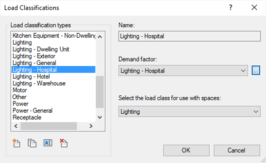
When placing equipment, it is important to make sure that each load is connected to the right classification. Not doing this important step could result in oversized panels, transformers, and switchboards, which could add tens if not hundreds of thousands of dollars to the electrical costs of the project.
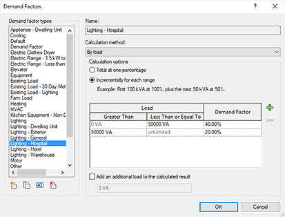
Load classifications also have specific demand factors. Receptacles have a demand factor of 100% for the first 10 kVA then 50% for every VA after. Hospital Lighting has a demand factor of 40% for the first 50 kVA and 20% for every VA after. Make sure you enter the correct demand factor!
To set your load classifications, you need to:
- Click on the family.
- Go to edit type.
- Click on load classification.
- There will be a list on the right of the different load classifications in the model.
- These classifications will be what appear on your panel schedules.
- Make sure that you have the right demand factor for each classification type, this sets connected vs. demand.
- Repeat for each family type – lights, receptacles, motor connections, heating, and cooling connections.
2. Understand Type vs. Instance Properties
Revit has two kinds of parameters; type parameters and instance parameters. Understanding when and where to use each kind of parameter is critical for an efficient workflow.
So what's the difference between the two kinds? Type parameters are consistent for each instance of that type in the project. When you place the family in your project, all instances of that type will have the same type parameter values. Change the value of a type parameter and all instances will update as well. Instance parameters, on the other hand, can vary for each instance. You can set different instance parameters for each instance in the project.

The parameters used in your Revit families should be mostly type parameters. These parameters should include load (VA), description, load classification, voltage, default elevation, cost, type mark, manufacturer, and comments. Note that you might need more than these for your specific project. Some of the parameters may apply to multiple families as well.
Creating multiple types for a specific family element allows you to change those parameters across your entire model. One good example would be creating four or five different VAV connector types so that when the load changes on one of the connector types, a single change to that type parameter updates all of the loads across the entire model. Type parameters could be used for lighting (2x4’s with different lumen packages), receptacles (GFI, standard, USB, above counter), junction boxes (VAVs, pumps, window shades), starters (pumps, motors), and data (1, 2, 3, 4, etc..., data drops, wall phone). Once you've defined your type parameter, the next step is to add the instance parameters. A good example of an instance parameter would be a graphical offset where you need to stack receptacles or fire alarm devices.
Defining your type and instance parameters takes setup time early in the process. It’s not a lot of time but it needs to be thought through. Specifically, you need to understand how those family elements are going to be put into the model. Where this really matters comes into play is on large projects. Small projects won’t see too much value, but large projects will really see the benefits of this workflow and family setup.
3. Use the Tab Key
The Tab key is one of those critically underused hacks within Revit. When you have elements stacked on top of each other or need to select a link, hover over the elements and use the tab key to highlight circuiting and switching, add wires to the drawings, or select the element you want to use.
The Tab key can also show you what is connected to a switch and what elements are circuited together. Once you see what is circuited or switched together, Revit will provide a context menu to let you place wire between devices. Here’s how to use it:
- Hover over a device that has been circuited.
- Hit the Tab key.
- Click the left mouse button.
- Use the context menu to change panels, add wires, and see what is circuited together.
4. Add Switch Legs
Adding a switch leg to light fixtures allows you to easily create and change lighting zones within a project. Once a lighting control zone has been established and light fixtures are tied to a specific switch, changing the name of the control zone or adding and removing fixtures becomes as simple as editing a circuit. This allows for easy manipulation of zones, labeling, and adding of zones. Here’s how you add switch legs:
- Select the fixtures that you want to be switched together
- Click the switch
- You can now edit the switch system, either adding or removing lights from the system
- Select the switch you want to control those lights
- In that switch under the instance property of ‘Switch ID’ enter the lowercase letter that you want to call that switch group
- Tag the switch and fixtures with their switch ID

See, it's as easy as that.
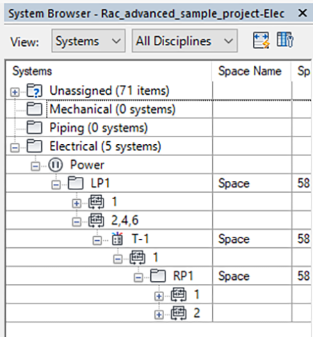
5. Use the System Browser
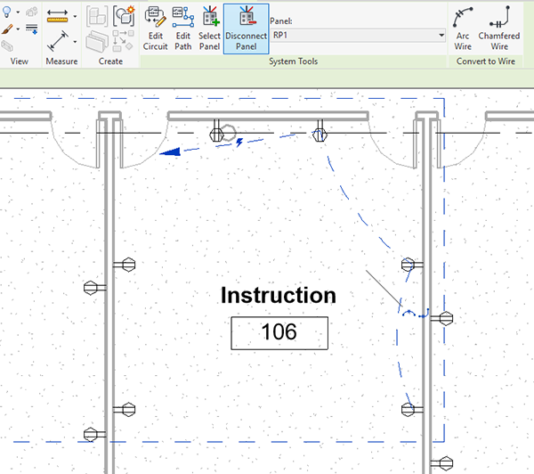
Ever found a random piece of equipment in your panel schedule? It likely had some generic name, making it difficult to identify. When this happens, use the system browser to hunt down that piece of equipment and figure out what it is. Hopefully, you don’t need to do this often during your project, or at least, you should need to if you are naming circuits as you go. However, when you do need to find that random piece of equipment, this is an invaluable tool.
The system browser shows the complete interconnection diagram of the entire electrical system. Finding a circuit that isn’t labeled properly is super easy using the browser. Likewise, you can easily find an abandoned panel that needs to be connected.
To track something down using the System Browser, just right-click the circuit and select "Show". A view will open showing you where the piece of equipment is located. From here, you’ll be able to properly name, relocate or adjust that specific piece of equipment.
And Remember. . .
Electrical engineering is hard enough. You don't need Revit to make that job any harder. Hopefully, these five tips will help make you much more productive in Revit.
Find these items helpful? I know they have saved me countless hours over the years. If you did and want to have a personal audit of your Electrical Revit process email me at kowabungastudios@gmail.com with the subject – “Electrical Revit Audit” and we’ll get started improving your Revit process and workflow.
About the Author
Dillon Mitchell is a licensed electrical engineer and has been using Revit for years. He is passionate about optimization and workflow improvement. Dillon has managed electrical departments designing close to 2 million square feet of educational and commercial buildings. Having designed electrical systems for 300,000-square-foot buildings, he understands that process matters. Every bit of improvement, short-cut, and time saver makes a big difference when working on projects at scale.
When not optimizing Revit or electrical engineering, Dillon enjoys running long-distance races (marathons and ultra-marathons) as well as Ironman Triathlons. Find him out on a trail or road testing the limits of personal endurance.
Get the Thursday Top 5
My weekly email with five interesting and useful links on BIM, design, and technology, plus a few laughs along the way. I send it every Thursday. Join the over 8,000 AEC professionals who already get it.