In this first part of a two-part series (read part 2 here), guest author Brian Kish highlights five key steps for designing extra-large projects in Revit. From hardware to model organization to drawing management, Brian shares the lessons he learned as the BIM Manager on the Medyan One Mall project, an extra-large retail complex currently under construction in Dubai.
With the introduction of Revit and other building information modeling (BIM) programs, the building industry has made huge strides in efficiency in the last decade. Many offices now have BIM standards and execution plans for the types of projects they typically work on. But what happens when an office wins a project significantly larger than any other project it has previously completed in Revit? Do the drawing and modeling standards developed for smaller projects still apply when confronted by a truly massive project measured in millions of square feet?
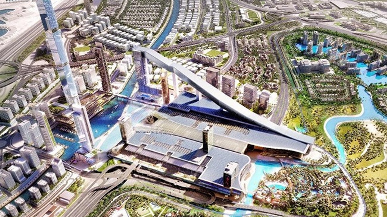
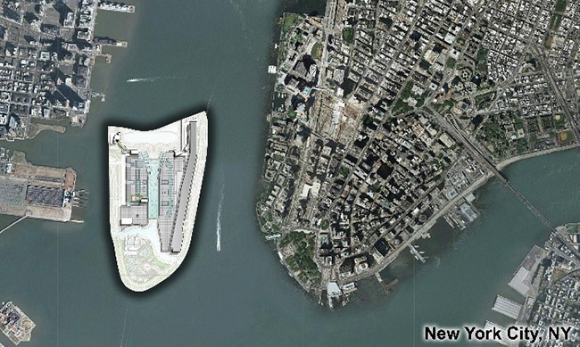
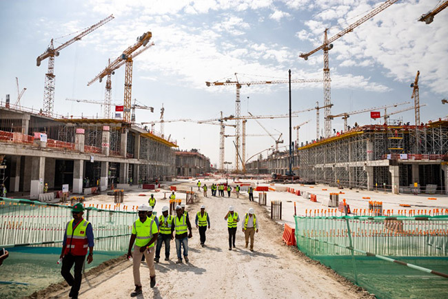
Meydan One will be one of the largest malls in the region with over 620 retail shops, 100 food and beverage outlets, and over 12,000 parking spaces, with one of the largest water features in the world. This project is significantly larger than any project AE7 has ever done, and revealed many valuable lessons.
This 2-part article discusses challenges and offers tips for successfully scaling up in Revit to complete a project that is larger than you have ever done before. Part 1 discusses what you can do before the project begins to set your team up for success, and part 2 outlines strategies for maintaining the project throughout the design process.
1. Hardware: Don’t handicap the project before it begins
as you prepare for a large project, hardware should be the first thing you organize. There are plenty of online articles that explain the hardware requirements for using Revit. These requirements are even more important when working on an extra-large project. Hardware upgrades are expensive up front, but the extra few hundred dollars for additional RAM or a faster processor are insignificant over the life of the project. In general, desktop computers will significantly outperform laptops, due to their upgraded video cards.
Remember that your staff’s time, not hardware, is a firm’s most expensive asset. To determine the benefits of upgrading hardware, estimate initial costs vs. time savings.
2. Strategize: Invest time when making significant modeling decisions
Determining how people will work on the project is crucial to the success of a project, especially an extra-large one. Too often, management makes important decisions hastily, and the consequences become apparent only after the team is committed to the strategy. Misinformed decisions become magnified on extra-large projects. It is important to have a series of project kick-off meetings that will help define workflow and highlight potential issues that may arise.
Some important decisions that AE7 made included:
- Where to host central files, and how will this affect workflow in different project phases and potentially between offices?
- What is the scale of drawings needed, including views across models, and how will that affect sheet count and model organization?
- What is the protocol for exchanging models with consultants?
Tables, charts, diagrams, matrices, and screen captures are all helpful tools to communicate these issues to colleagues who are not Revit-savvy but have a stake in the answers to these crucial questions. These documents are also useful in explaining past decisions to new project members who are unfamiliar with the project and model management.
3. Model breakdown: More models do not mean greater efficiency
On small and medium-sized projects, one model can encompass the entire project, but with larger projects, a tendency to break projects into many different models may lead to more confusion than efficiency. Many people on a project team will have an opinion on how to break down a Revit model. Everyone from drafters to principals holds an opinion on when and how to break apart models. With that in mind, how models are broken down is crucial, if not the most important consideration in extra-large projects, and therefore should be carefully considered.
While it is easy to split a Revit file, it is almost impossible to put it back together. The Meydan One Mall was split as little as possible because having many links in a model hinders model opening times and performance. Instead, turning off worksets that were not needed to complete a specific task enhanced performance without splitting. New models should only be created when performance issues that impact time spent cannot be improved through other methods. Here are some factors to consider before splitting a model.
A. Phases of the Design Process
The number of models will typically increase as the project progresses. Extra-large projects very rarely go as planned, making it nearly impossible to predict the number of models needed in the end. The Meydan One Mall project did not include a breakout projection. Instead, workflow issues that arose during drawing production were addressed through brainstorming and testing various solutions. Do not break out a model close to a deadline, in case of unforeseen consequences. A vetted solution is best implemented after a drawing submission.
B. Location of the project team
What is the estimate for staffing needs during each phase of the project? Is the project team located in a single office, or spread across different continents? How wide is the range of Revit experience among team members, and what tasks will each team member be completing?
The answers to these questions will influence how to break down project models. It is ideal to limit the number of people in a Revit model to between six and eight people; however, at points during the final hours of a deadline on the Meydan One Mall project, Revit functioned satisfactorily with fourteen to sixteen people working in the model.
If a team is split between different offices, the team may want to break out office-specific models dedicated to particular elements of the project. It is common for multiple offices to work on an extra-large project together. Hosting specific files locally will help with model performance, opening time, and syncing time. It is critical for decision-makers to consider model breakdown when deciding what parts of the project each office staff will develop.
It may help to split up the model to prevent damage in case something gets deleted or corrupted in the process. It will limit the number of elements that are affected. However, it is best to manage this risk with staff training and mentoring.
C. Splitting by geography or component types
A project will always have discipline-specific models, like structural, site, and electrical. There are generally two different strategies for breaking apart models when you exclude accommodating different offices. Within each discipline, either break down the models spatially—where those elements are located in the project—or by category of the components.
The first option is to split the building in half, quarters, or by floors: East and West, North and South, Level 0 to 10 and 10 to 20, and so on. Depending on the shape of the building, this can work well and is easy to understand. A downfall of this approach is that families such as wall types and ceiling types, as well as view templates, must be managed across multiple models. This requires great diligence to ensure consistency.
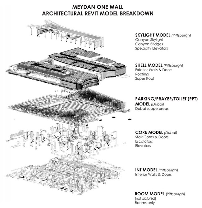
The Meydan One Mall models were split by keeping categories of objects in the same file. These included a vertical transportation model, a ceilings model, a walls & doors model, a rooms model, and an exterior shell model. This allows for easier management of families because they only live in one model. With this approach, however, making changes in one area of the project often requires opening several different models to complete the work. Another consideration for this approach was how types of families interact with each other. Certain families require a host, which required creating these as “face-based” families if the host lived in a different model.
Late in the design phase, a question arose if it was a good idea to change the model-breakdown strategy from a component-based strategy to a geography-based strategy to allow for half of the model to be hosted in the Dubai office and better accommodate the construction schedule. A study was conducted and we concluded that it was best to keep this particular model unified as we had originally intended. Instead of splitting, we purchased additional desktops to be used as remote access machines.

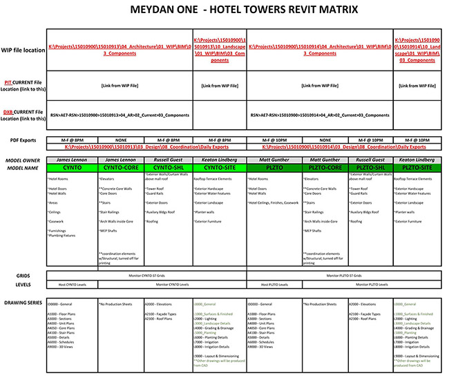
4. The Model Matrix: A Key for Communication
However you decide to organize your models, communication is key to allowing them to function as planned. The more models, the more confusing a project can become. Always update the entire team, including consultants, when breaking out a new model to avoid questions as to why part of the model disappeared.
On extra-large projects, AE7 maintains a model matrix explaining all the models for the entire project. This matrix is given to all new team members. The matrix includes:
- each file’s name and owner. Listing the owner lets team members know who to contact if there is an issue with that model.
- the model elements in each file. This list is important for finding elements like escalators or stairs.
- the Drawing Series included in each model. There is nothing more frustrating than opening several models before finding the drawing sheet needed.
- a list of worksets and links within each file.
- the file path to locate each model.
5. Organize Your Drawing Packages
It is important to think about where the drawing sheets will be located. One approach is to create a single file containing all the drawings for the project. This file would contain no model elements at all, just sheets and annotations. However, this method meant the drawing file would have a lot of linked models and make model opening times very slow. A positive to this approach is that it allows printing all the drawings from a single file. Furthermore, because all the drawings and views are in this model, it is very easy to do callouts to details or other views, unlike the approach locating drawings alongside the elements they portray.
Unfortunately, this approach comes with drawbacks, too. The model takes a long time to open because of the large number of links that must be loaded, and it takes a long time to sync because there are many people in that file. All the dimensioning, tagging, and annotating are done on linked elements. This can cause lost dimensions and keynotes to not populate properly. Finally, during deadlines, the file will likely become corrupted because most people will be working on sheets at that point.
For Meydan One Mall, splitting drawing sheets across several models was the best solution. It is a solid approach for splitting team members across different models and maintaining model performance. This keeps the sheet in the same model as what it is documenting. Keep stairs and elevator drawings in the vertical transportation model and keep partition plans and door schedules with the walls and doors. This allows for easy adjustment of elements when working on a sheet. However, Revit does not let you do callouts, sections, or elevations tags for views in different models.
Firms have various workarounds for referring to views in other models. One option is to create “fake callout” detail items, manually entering the drawing number into the callout bubble. Another approach is to create “dummy views” within the model reference that have the exact same number as the views in the linked file. These approaches work well until details move between sheets or change numbers.
The primary approach AE7 used was to create a series of views that contained reference annotations in the “referring to” model annotations and use the “link view” function to make them visible in the final view. Unfortunately, sections, elevations, and callout bubbles are not visible in linked views, though references are. Annotations made using the “view reference” annotation type can be made to look like sections, callouts, etc. This will allow for drawing numbers to update automatically.
By taking these factors of hardware, personnel, and model organization into consideration before a project begins, you will have a reliable structure in place as the complex process of design throws hurdles in your way. These considerations become even more crucial as projects scale up in size and will prepare you for even larger projects in the future.
In Part 2, we explore how to maintain those systems during the design process.
Get the Thursday Top 5
My weekly email with five interesting and useful links on BIM, design, and technology, plus a few laughs along the way. I send it every Thursday. Join the over 8,000 AEC professionals who already get it.